Ultrasonic Testing
Ultrasonic testing is often performed on steel and other metals and alloys, though it can also be used on concrete, wood, and composites, albeit with less resolution. It is used in many industries including steel and aluminum construction, metallurgy, manufacturing, aerospace, automotive, and other transportation sectors.
Ultrasonic methods of NDT use beams of mechanical waves (vibrations) of short wavelength and high-frequency, transmitted from a small probe and detected by the same or other probes. Such mechanical waves can travel large distances in fine-grain metal, in the form of a divergent wave with progressive attenuation.
The frequency is in the range of 0.1 to 20 MHz and the wavelength in the range 1 to 10mm. The velocity depends on the material and is in the range of 1000-6000 m/s.
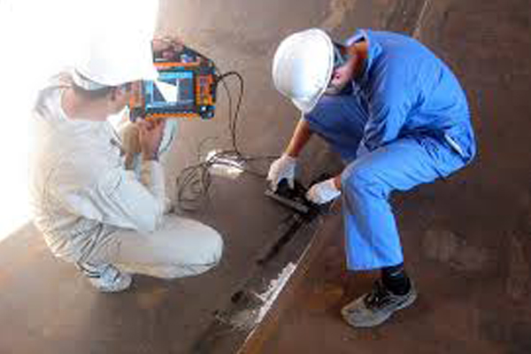
In ultrasonic testing, an ultrasound transducer connected to a diagnostic machine is passed over the object being inspected. The transducer is typically separated from the test object by a Couplant (such as oil) or by water, as in immersion testing. However, when ultrasonic testing is conducted with an Electromagnetic Acoustic Transducer the use of Couplant is not required.
The technique detects internal, hidden discontinuities that may be deep below the surface. Transducers and coupling wedges are available to generate waves of several types, including longitudinal, shear, and surface waves. Applications range from thickness measurements of thin steel plates to internal testing of large turbine rotors.
Most non-porous, resilient materials used for structural purposes (steel, aluminum, titanium, magnesium, and ceramics) can be penetrated. Even large cross-sections can be tested successfully for minute discontinuities.
Ultrasonic testing techniques are widely accepted for quality control and materials testing in many industries, including electric power generation, production of steel, aluminum, and titanium, in the fabrication of airframes, jet engine manufacture, and shipbuilding.
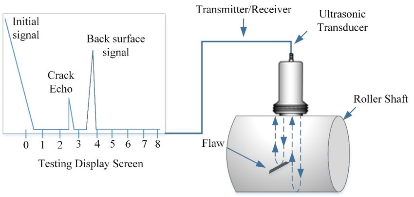
Usually, pulsed beams of ultrasound are used and in the simplest instruments a single probe, hand-held, is placed on the specimen surface. An oscilloscope display with a time-base shows the time that it takes for an ultrasonic pulse to travel to a reflector (a flaw, the back surface, or another free surface) in terms of the distance across the oscilloscope screen – the so-called A-scan display. The height of the reflected pulse is related to the flaw size as seen from the transmitter probe. The relationships of flaw size, flaw distance, and flaw reflectivity are complex and considerable skill is required to interpret the display.
Complex multiprobe systems are also used with mechanical probe movement and digitization of the signals, followed by computer storage; methods of computer interpretation are developing rapidly.
There are several forms of mechanical vibration, depending on the direction of particle movement in the wave motion, and so there are several forms of ultrasonic waves, the most widely used in NDT being Longitudinal and transverse (shear) waves.
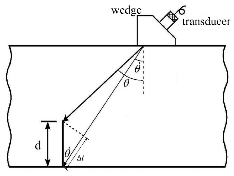
By suitable design of probe, ultrasonic beams can be introduced into solid material at almost any angle.
Longitudinal waves will also travel through liquids and a common technique is to immerse the specimen in a large tank and use a stand-off probe with a mechanized movement. With such equipment, alternative methods of displaying the signals are possible and a two-dimensional ultrasonic image can be produced (B-scan and C- scan displays).
Generally, a single probe acts as both transmitter and receiver, so that inspection can be done from one side only of the specimen. Large-grain materials such as austenitic steel welding, copper castings, etc produce severe attenuation and scattering and are at present difficult to inspect with ultrasound, but large thicknesses of fine-grain material such as forged steel can be tested without difficulty.
Because the usual indication of a flaw is a pulse on an oscilloscope trace, flaws must be characterized and also sized. New techniques such as time-of-flight diffraction, TOFD, have been developed to assist this technique.
Ultrasonic attenuation and ultrasonic velocity measurements are used to study various material properties.
The use of ultrasonic for sizing flaws
Once flaws have been detected it is often desirable to determine their size. For flaws smaller than the ultrasonic beam width, a pseudo-sizing can be obtained by comparing the flaw signal amplitude with that of a reference reflector (flat-bottomed or side-drilled hole) at the same range. When the flaw size is greater than the ultrasonic beam width, conventional probe movement sizing techniques can often be used to provide an estimate of flaw size. The maximum amplitude technique uses a measure of the probe movement between the maximized signals from flaw extremities to size flaws. The 6 dB and 20 dB drop techniques use the reduction in the signal amplitude from the flaw as the probe passes over the edge of the flaw as an indicator of flaw dimensions. However, the interaction between the ultrasonic beam and flaw, depending as it does on flaw nature and orientation, limits the effectiveness of these techniques, when dealing with complex and is- orientated flaws.
Techniques that make use of the diffracted signal from the flaw extremities to locate and size flaws are most effective in sizing planar flaws. The time-of-flight diffraction (TOFD) technique uses the ultrasonic transit time between probe(s) and flaw extremities to locate and size flaws. Flaw sizing accuracies of better than ±2mm can be achieved with optimized techniques (see also Ultrasonic advanced methods).TOFD phased array etc.
There have been many developments and refinements to the fundamental ultrasonic technique to cater for improved performance and/or results.
For example, AUT refers to Automated Ultrasonic Testing. Although this is a generic term that relates to the computerized collection of ultrasonic data, the three-letter acronym AUT is now used to refer specifically to the automated ultrasonic inspection of pipe girth welds. Such systems have two sets of ultrasonic probes scanned circumferentially on either side of the weld. The sets of probes are selected to provide coverage of specific zones of the weld and the fusion face.
Time-of-Flight Diffraction – TOFD – is an ultrasonic technique that measures the time of flight of a pulse as it travels from a transmitting probe to a receiving probe. Divergent beams are used and it is necessary to scan the TOFD probe pair over the flaw for the technique to function correctly.
What distinguishes the technique from a standard pitch-catch configuration is the D which stands for diffraction. The technique relies on the detection of the diffracted sound wave which is generated from both the top and bottom edges of a planar defect.
The time of arrival of the diffracted signals from the flaw tips is measured concerning the probe firing time. Time measurement can be done to great accuracy. The combination of this accuracy and the fact that the scattering source is the flaw tip forms the basis of a highly accurate sizing technique.
A phased array is a name given to a special type of ultrasonic probe.
An array is a group of transmitters, receivers, or transmitter/receivers, generally called array elements. When used as a transmitter, firing the elements at different times can lead to interference between the sound waves produced by each element. This interference can be both constructive (waves add together) and destructive (waves cancel).
It is this interference that gives the array probe its main advantage – the ability to change beam shape and angle depending upon the timing at which elements are fired. When an array is used as a receiver, the difference between the times at which a pulse arrives at each array element contains information about the location of the pulse source.
Ultrasonic Thickness Measurement
These systems give for the sorting of fabric, supported variations in hardness, heat treatment, grain structure, case depth and material grade. Manual, semi-automatic and totally automatic (inline/offline) sorting systems ar created offered, supported the need.
What can be measured with ultrasonic thickness?
Ultrasonically measuring almost any common engineering material is possible. Metals, plastics, composites, fibreglass, ceramics, and glass can all be gauged with ultrasonic thickness gauges. Extruded plastics and rolled metal can also be measured on-line or in-process, as can individual layers or coatings in multilayer fabrications. Levels of liquid and biological samples may also be measured.
How ultrasonic thickness gages work?
Ultrasonic thickness gages work by means of very precisely measuring how long it takes for a legitimate pulse that has been generated via a small probe referred to as an ultrasonic transducer to tour through a check piece and reflect again from the interior floor or far wall. due to the fact sound waves mirror from limitations between multiple materials, this measurement is usually made from one side in a “pulse/echo” mode.
